I’m in various stages of completion for several guitar effects at the moment and I’ll certainly try to write a post for each of those in turn. However, I first figured I should post about my guitar effect PCB test box I put together. I by no means first came up with the idea. Paul of DIY Guitar Pedals in Australia is who I first saw use & recommend one. In searching around for further ideas, I came across some notes on DIY Stomp Boxes about adding the probe, which can be used in diagnosing PCBs that aren’t working.
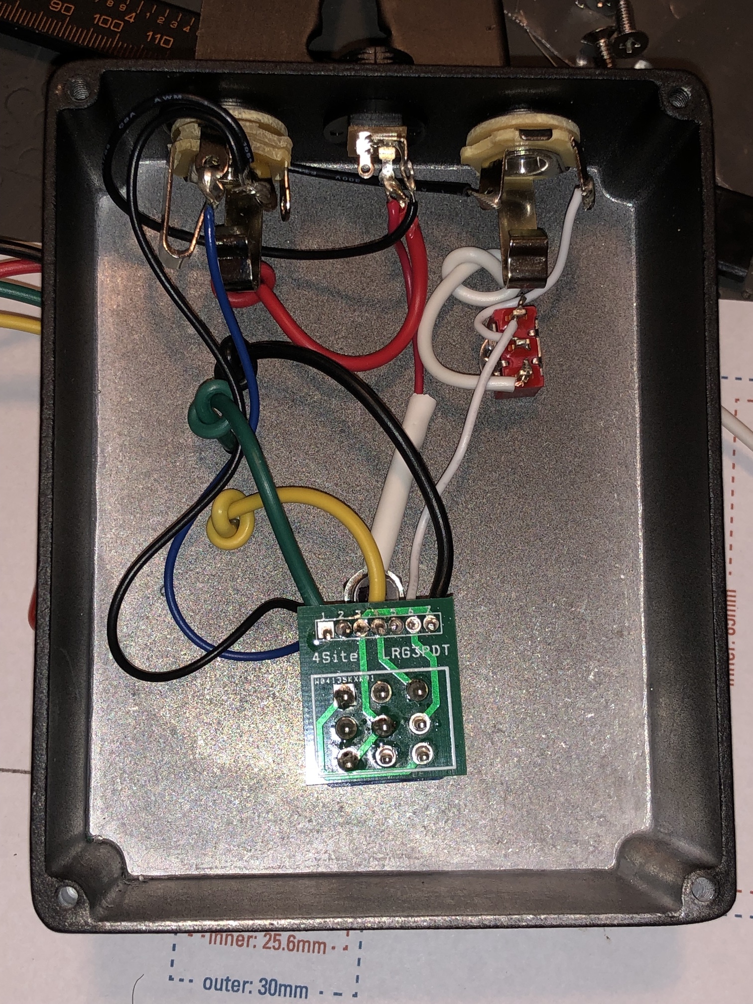
As you can see, I went with a fairly large enclosure for this project. As it’s really just the off-board wiring standard to most any pedal project, with no circuit board, this is somewhat a waste of space. However, I wanted to leave a bit of space for potentially adding some more features at some point in the future1. This is a powder-coated, aluminum enclosure which is not at all necessary for this, as the wiring is outside so the metal box isn’t shielding anything. So the enclosure was a bit of a splurge. But as Mammoth currently sells these 1590BB enclosures powder coated for under $10, it’s not exactly a bank-buster. The entire test box is less than $25, and many of the parts I already had in my parts bin.
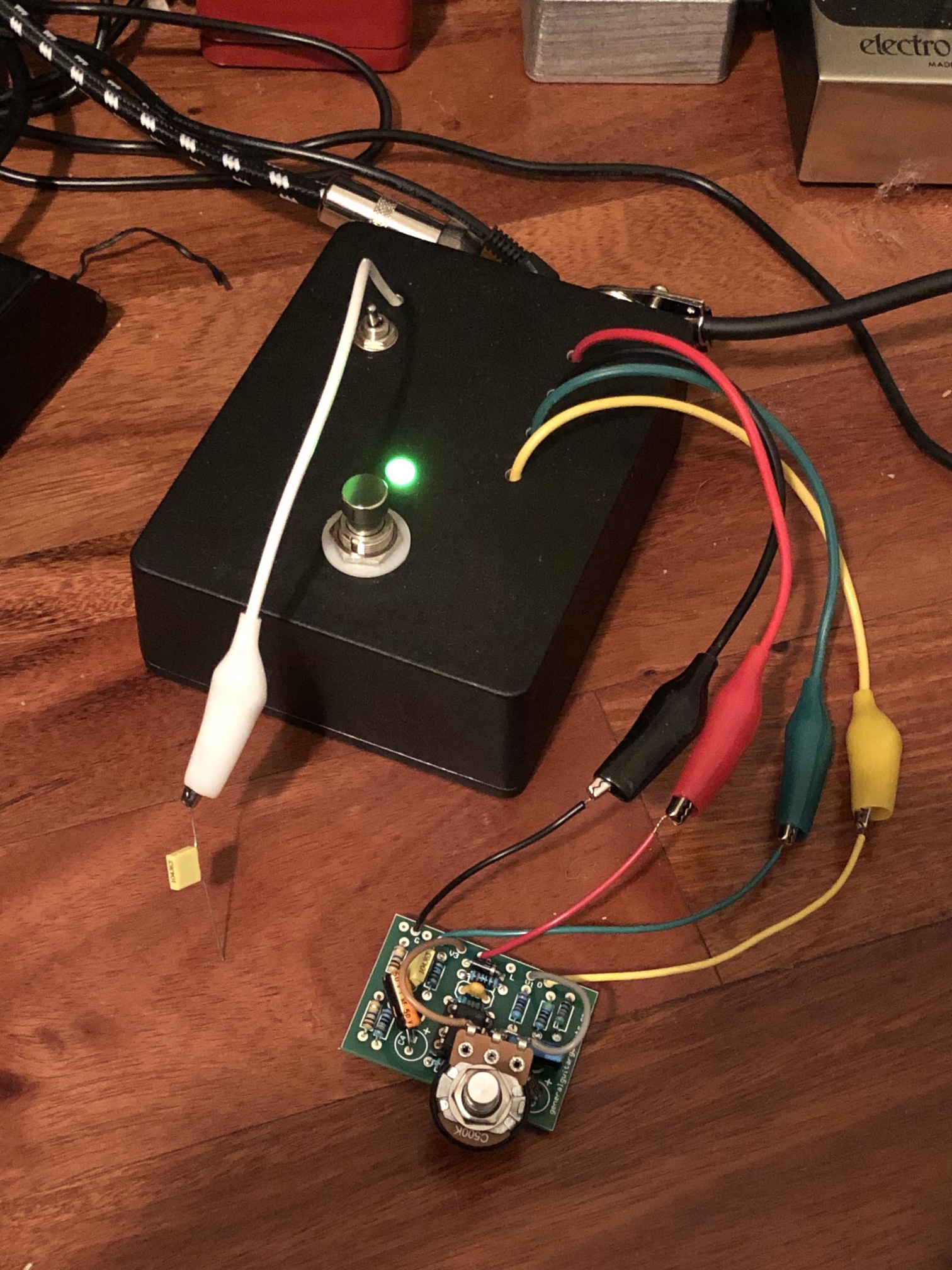
I cut up some cheap alligator clips I bought off of Amazon.com to use for the connectors. They have little covers over the clips, so they work quite well even when connecting into closely spaced wiring leads. I did knot these just inside the box to provide some strain relief (though it’s not as though this thing is getting roughed up much). I used a Mammoth Electronics bypass wiring board just to simplify things a bit. I tend to use a standard wiring colors for all my projects: red for 9v, black for ground, green for signal to board, and yellow for signal back from board.
The one trick my box has is that I added a toggle switch to use a testing probe. This switch basically hi-jacks the signal return (yellow) and connects the probe (white) directly to the box output jack. So if signal isn’t coming back from the circuit, I can flip this switch and then use the probe (which is nothing more than a 1μf capacitor) to touch along the circuit to trace where the fault is. It’s very simple but incredibly helpful.
So to quote Paul of DY Guitar Effects, if you’re going to even build just more than a couple of guitar effects yourself, you’re going to want to build something like this. It’s so invaluable to be able to test your PCB as soon as you get the components installed but before you try to complete all the off board wiring & stuffing it into an enclosure. It’s also extremely fun to hook up to a breadboard and test that way!


I was wondering if on the mammoth electronics bypass wiring board if you actually soldered those 9 “prongs†that the foot switch actually pushes through. I just finished their deviater octave fuzz and it’s not turning on lol. Signal passes through when it is off but nothing when it is on. It’s my first kit build, and I’m hoping I did something silly instead of frying the board. Thanks
Hi Matt! Yes, I used a PCB-style 3PDT footswitch. If you have a solder-lug style, it probably won’t fit into the openings (though they are quite large, as I recall). I soldered each and it does take a fair bit of solder to fill up the holes.
As for the pedal not working, don’t get too discouraged. If you haven’t already figure it out, I’d start with the off-board wiring between the switch/or switch PCD and the main effect PCB. My very first build, I managed to swap the input and output jacks. If your LED comes (assuming you have one), then you’re at least getting power. You can try using a capacitor like I’ve described above on the cable to your amp and probe the circuit (just turn the amp down because it can get loud!).
Lastly, you can post some images on pedal builder forums. Folks that know a lot more than I do are great helping to troubleshoot issues.
Hi! Hopping on this quiet thread, hoping to revive it for a little help. I’m a beginner and very much stumbling through all this.
I’ve built a test box and am currently trying to test this board (https://www.stewmac.com/freeinfo/i‑2350–2355/i‑2354/i‑2354_Interval_Fuzz_0920.pdf).
What I’m confused about is that you, Paul, and everyone else who I’ve seen build and use a test box have effect boards with 4 offboard connections: power, ground, signal in, signal out. Mine’s got 8 — these four, plus an input jack ground connection, an output jack ground connection, a ground connection for the footswitch, and a connection for something labeled “SW” on the footswitch board.
For the life of me, I can’t figure out what to do with these extra. Do I connect them all to the test box? Do I leave them on the board but disconnected from the test box? You seem to have some jumpers on your board, is that what I’m missing?
As it stands now, I’ve tried testing this board 2 ways: with the extra 4 offboard wires not connected to the test box; and with the extra wires removed from the board. Each time, the effect worked for a second or so before fading out and not coming back.
Hi Andrew! So, yes, all your ground wires can be connected together. The SW looks like it might be just the LED connection in this setup. Might be good to e‑mail StewMac’s support account to verify, though.
Thanks for your quick response, Jason!
Noted, connect all grounds. Makes perfect sense now that I think about it, actually — unconnected its just a big ol’ break in ground.
I haven’t heard back from StewMac yet but I googled a bit and it looks like you’re right regarding the “SW” pad. But it begs the question… when testing, what do I connect that to? Or do I leave it alone?
This is super helpful, thanks! Also, I know this is probably a super basic simple question, but I’m assuming doing this only works with the pots connected to the pcb? I’m working on a few builds right now with PCB mounted pots so I’m just trying to figure out the logistics of testing those.
@Andrew — Oh, I totally missed the question at the end of your comment from last year! You’ve probably already figured it out since then, but I did take a look at the Interval Fuzz’s instructions. I’m not 100% sure, but I think this is how you’d wire it based on my tester color conventions (that is, Red for 9v hot, black for ground, green for signal to board, yellow for return effected signal from board). I’m not 100% sure about the DC jack they use and which is the ground lead (that is, the black and red may swap if I’m wrong).
@Jake — Yeah, you typically have to have any pots on the board. If you have a breadboard, you could put them on that and them just temporarily solder them to the pcb (or some other temporary means of connection). I have loosely mounted them in the enclosure and then soldered them to a PCB, but then taken the whole thing out for testing in the past. That depends on the PCB and enclosure, though, I suppose.